


100MW solar panel production line composition:
Production line specification:
1. 100MW module production line (1).
2. Beat: ≤45 seconds/block.
3. Type of panel produced: conventional full-cells/half-cells solar panel.
4. Solar cell size: 166-210mm.
5. Solar panel size: L(1956~2300mm) x W(990~1200mm) x T(25~45mm).
6. Solar ribbon type: flat welding ribbon;
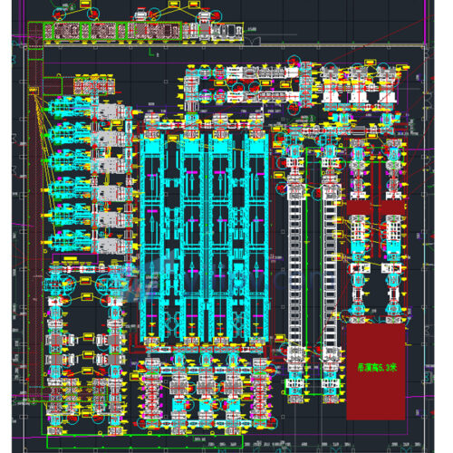
Production line overview:
Before the lamination: glass loading area, EVA loading area, typesetting, bus soldering area, EVA and backplane loading area, pre-layer EL/VI inspection and repair area, stack (production line component caching process), conveyor system
After lamination: trimming and gluing and framing area, junction box welding and gluing area, curing line, cleaning and testing area, binning area, conveyor system
Specifications:
1. The assembly line is compatible with the production needs of double-glass and ordinary modules. It adopts a modular design. To facilitate installation and maintenance, each module unit must use a frequency converter to regulate the speed to 50HZ.
2. The transmission belt support beam has a high-strength aluminum profile and anodized surface, which is beautiful and durable. Motor mounting plate: Q235 iron plate, surface sprayed with plastic. Rack: Assembled from 4080 aluminum alloy; modular rack design for easy installation, debugging, and transportation. Safety maintenance: Timing belt replacement is simple, easy to operate, and equipped with safety protection.
3. All steel parts should be protected from rust.
4. The conveyor belt layer uses green cloth-covered synchronous belts to ensure high-temperature resistance and no belt marks on the coated glass surface. The transmission belt is a wear-resistant material that will not damage the coating layer on the front of the component. The gap between the active pulley and the belt at the operating station should be as small as possible to prevent fingers from getting involved.
5. Assembly line height and adjustment range: height 950±50mm, height difference between adjacent ends ≤2mm;
6. The speed of the front section of lamination is adjustable from 15-25 meters/minute; the speed of the rear section of lamination is adjustable from 15-25 meters/minute;
7. Control: adopt PLC control, sensor + electrical control. Sensors are used to slow down movement and stop it.
It has interactive chain control and warning functions to ensure safe and reasonable operation.
8. Cooling of components after lamination: Install silent cooling iron blade fans from the post-lamination assembly line to the trimming station, with more than two discharging units, more than two transition units, and more than two rotating units;9. The motors and other mechanical devices have good performance and service life and are easy and fast to maintain.
10. Provide electrical design drawings. The layout of electrical components is neat and standardized. All wires and components are concentrated in the control cabinet. Each element is annotated. The wire and pipe numbers are marked and correspond to the drawings. The starting position of the line in the drawings needs to be marked. Bits come from which page and which line or which page and which line they go to. All equipment should have a good grounding, and the emergency stop switch should use a 24V low-voltage power supply.
11. Equipment utilization rate of the entire line: ≥99.5% (failure time includes instant failure stop time, failure time, and cumulative statistics of failure time of each process).
12. Equipment software permissions: operators, engineers, administrators, all software backup and installation disk production. The operation interface supports Chinese (English) switching. The operation screen has a screen saver function. You must enter a password to enter the interface in the screen saver state. Interfaces such as parameter calibration and other interfaces require password input.
13. Use the three-color light with a buzzer; the alarm sound is a buzzer, and the function of feedback is abnormal information;
A. Green light: The equipment is operating normally.
B. Yellow light: Equipment is stopped, maintained, or in manual mode
C. Red light: equipment abnormality or failure, alarm14. The test equipment’s data is stored to ensure that it will not be lost in case of a power outage.
15. The laminator’s front loading unit ensures accurate loading of laminated parts: mechanical correction mechanisms and photoelectric positioning are used in the horizontal and vertical conveying directions, and the correction accuracy is less than ±2mm (excluding material factors).
16. The working line body has OK and NG buttons and a memory function. A set of buttons is required on both sides of the two-person working line body, which is also equipped with a material placement box.
17. The folding channel angle is close to 85 degrees.
18. The manipulator does not shake when it starts or stops. It has the functions of material detection and limit protection.
19. Line lifts must have safety fences and emergency stop buttons.
20. Aisles use cylinders or manual telescopic/folding channels.21. When using a magnetic switch for the cylinder, tighten it appropriately to prevent the magnetic switch wire from being broken.
22. The transplanting servo speed can be adjusted on the operation screen.
23. The frame thickness is 25-45mm. Curing and classification support suction and grabbing functions. It is only suitable for frames with C sides.
24. The assembly line conveys smoothly, and there are no scratches, belt marks, roller marks, or damage on the surface of the components.
25. The IV testing equipment is equipped with a regular assembly line before feeding;
26. A normalization assembly line unit is configured before the components enter stand-alone equipment such as stack welding machines, laminators, and power testing instruments.
Solar panel conveyor specifications:
1. Transfer arrival requirements: All transfer units apply to component types within the component range
2. Transmission speed: theoretical speed 15-25m/minute
3. Transmission height: 950mm ±50mm
4. Transmission unit spacing: 50 to 100mm
5. Transmission stability: There is no apparent jitter or position deviation during component transmission.
Copyright © YiLi Pv Tech Ltd.
Opening Hours:
Monday – Friday 8am – 9pm
Mob&Whatsapp: +86 18813913430
Email: sales@yilipv.com
Address: Room 918,Building 2,Wujin Wanda Plaza,Wujin District, Changzhou City, Jiangsu Province,China